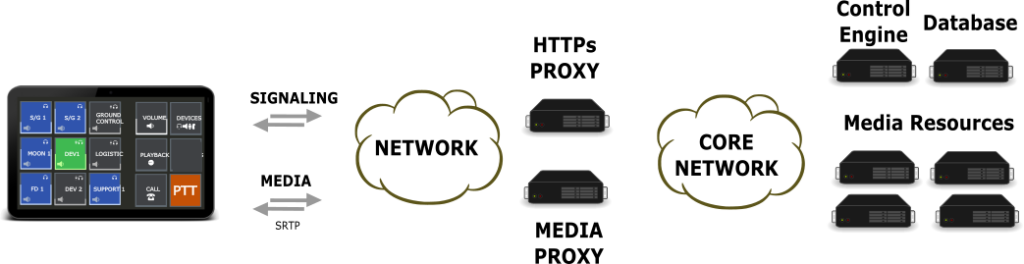
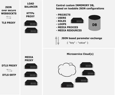
The openvocs architecture is a traditional client server architecture using two types of transmission protocols, one for signaling events, the other one for media distribution. The 2 types of protocols are reflected within the server architecture, which is using a HTTPs server and a Media Relay Server.
The network itself is undefined and may be routed or a flat VLAN based network. Both scenarios needs to be supported.
Signaling and Media protocol are the core definition of openvocs. These protocols transmit events and media between client and server.
To allow lightweight and simple client instances the following prerequisites are set. Openvocs performs media mixing within the backend and provides the individual mixed media stream over one media connection to each client. This allows to reuse common VoIP technologies for media distribution. In addition it supports a simple interface for client applications and therewith a wide range of potential client implementations.
Defining the protocols between Client and Server backend is enough to allow different vendors to implement different client as well as server instances. Our goal is a minimal definition of the environment to allow maximum flexibility in actual implementations.
Signaling messages are transmitted as JSON over websockets. Signaling is alligend to the events a user may initiate at the client. The subset of events is defined within the openvocs API description. Media messages are transmitted via DTLS-SRTP a secure industrie wide used standard for audio transmission.
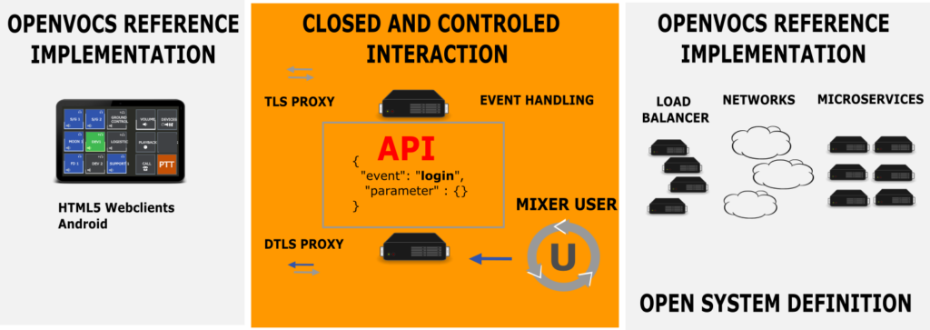
Definition of Client Server interaction is the core of the openvocs protocol. It allows an open connectivity for different kind of client implementations, with an open system definition, allowing different kind of system implementations. Our definition allows both an open connectivity with an open system design. Nonetheless this kind of definition in not enough to build a VoCS system, therefore we implemented a reference system with a lot more detail definition for the systems.
Reference Architecture
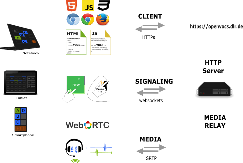
To build the most lightweigth client possible, openvocs uses an HTML5, CSS, JavaScript based webclient with WebRTC based media distribution.
Our reference implementation focuses on the most high level implemention to build a VoCS system. The client is virtual it instantiates within the webbrowser. A client is always upto date, as it is basically a website, which is loaded from a HTTPs server.
User interaction within the system e.g. selection of participation states for Voiceloops or PTT to transmit audio are converted to some events. These events are transmitted over the signaling channel to the server. As signaling channel the websocket protocol is used. To frame events a JSON structure is used. Events are transmitted as JSON over websockets.
For media transmission SRTP is selected. This is the secure version of the RTP protocol and widely used within the telekommunication industrie. At the client side WebRTC is used to transmit the audio from Microphone to the backend, using the SRTP channel.
The arichtecture selected is based on Webtechnologies to support the High Level implementation of the reference architecture. Nonetheless the protocol suite is quite simple and allows dedicated client implementations based on the usage of JSON over websockets, as well as WebRTC based communication channels.
Breaking down the architecture one step further, the backend needs to be defined in terms of functionality. The High Level description above gives a good hint about the Client Server architecture to connect clients and backend, but to provide VoCS services a backend must support the VoCS specific building blocks.
VoCS specific building blocks are an Authentication and Authorization backend as well as a mixing backend.
For Authentication and Authorization the openvocs reference implementation uses an in memory database based on JSON values. This database allows multi domain usage and is multitenant. It allows different projects within a domain and is Multimission ready.
The mixing backend is build up of microservice based mixer instances. Each proxy connection will use a dedicated mixer to mix the audio stream an user selected over its interface.
The microservice cloud is using Multicast based mixing of Voiceloops.
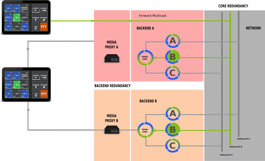
Media within the system is transmitted over Multicast Voiceloops. Each Voiceloop is using a dedicated Multicast IP. All trafic for a specific Voiceloop will be forwarded to that IP. Forwarding is implemented within the media proxy and transparent for clients. Clients communicate with the proxy and the proxy is forwarding incoming and outgoing media to the client. When a Voiceloop is selected for talk, the media proxy forwards that Voiceloop to the specific Multicast group.
During login to the system each client will be associated with a dedicated Mixing service. The mixing service is basisically a Multicast mixing node. Each Voiceloop a user selects will be mixed and a single stream of audio is transmitted to the proxy, which forwards the audio back to the client.
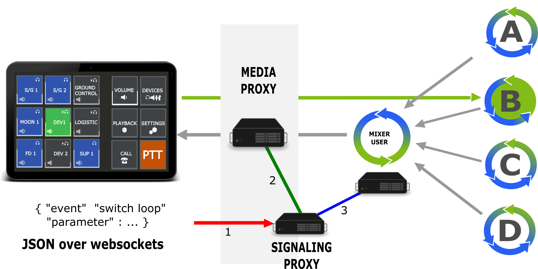
The above image shows the selection of Voiceloop DEV1, which is mapped to Multicast Group B. In addition some Loops A,C,D are selected for monitoring and mixed within the user’s mixer instance. The mixer instance forwards the stream to the proxy, which again forwards to the client. Switching is implemented over an internal API, which is not shown here for simplicity. This mixing functionality implements the core of a VoCS system, multiparty multiconferencing. Our solution using a media proxy to forward streams to and from the backend allows simple client implementations. A client connection is basically a (voice) call to the system, but instead of calling to a conference room, the call is transmitted to a custom mutliconferencing backend.
Switching within the system is quite simple. The Signaling proxy receives a command from the client, checks if the user is allowed to perform the switch and switches the media proxy, or media mixer dependent on the loop state. A monitor switch means to either switch on or off monitoring for a multicast group and therewith the reception of that Voiceloop. Switching a Voiceloop to talk means to switch the media proxies outgoing stream to the Multicast group of the Voiceloop.
The reference architecture contains an HTTPS capable server, which has a signaling proxy implementation enabled, combined with a Media Proxy server, a Multicast based backend network and a Mixer Cloud. The Mixer Cloud is actually a set of mixer implementations, which register at the signaling proxy. Each mixer is able to serve one client. The system scales with the amount of mixer services. If a system needs to provide 100 positions in parallel, the cloud must be configured for 100 mixers. Signaling proxys are Webservers with HTTPS and Websocket support. Within the Webserver a VoCS implementation instance is loaded, which provides all signaling event handling as well as user authentication and authorization capabilities.
This setup is highly flexible and adaptable. For operational use cases we deploy 2 instances in parallel and each client connects to both instances. Therewith every service is build up redundant.
Our setup is as flexible as it could be to provide VoCS services. It is highly scalable, based on the amount of mixer instances used and able to provide redundant implementations over the client interfaces.
openvocs audio architecture
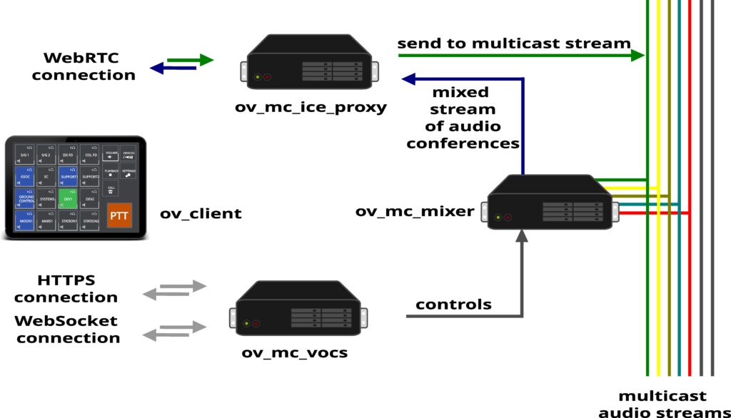
Openvocs audio architecture is based on multicast network transmission and routing of audio streams. Each multicast IP:Port combination represents a dedicated Voiceloop. Assignment of Voiceloop to IP:Port combinations is done within the core service of openvocs, ov_mc_vocs.
Client to backend audio architecture is based on WebRTC media transmission. WebRTC is a media standard integratet in todays webbrowser environments and specified and described in detail at https://webrtc.org/ Using WebRTC for client termination implies to be compliant to the WebRTC standard within the backend. WebRTC uses a DTLS based secure communication channel to transmit precoordinated media streams. In case of openvocs the precoordinated media type is: Opus encoded audio.
ov_mc_ice_proxy is used to terminate WebRTC connections as connection endpoint within the openvocs system. Each Client Endpoint will have a dedicated ov_mc_ice_proxy endpoint counterpart, as the communication between client and backend is unidirectional.
ov_mc_mixer is used to connect to several multicast audio streams in parallel and to mix the audio of all of the connections it is currently connected to. This way the media stream for some client Endpoint is build. The mixed media is transportet to the ov_mc_ice_proxy connecting the client endpoint, secured using SRTP and transported as WebRTC media stream back to the client.
A decicated ov_mc_mixer instance and the logical endpoint within ov_mc_ice_proxy form a user session for the client endpoint. Every audio aspect of the connection is handled within that session.
Forwarding audio to some multicast stream is done via the ov_mc_ice_proxy instance. Media within the backend is per definition Opus encoded audio.
Switching a Voiceloop – what will happen?
Once a session for some endpoint is set, which means the WebRTC media connection handling is done as well as a mixer is assigned to the client endpoint, a user may switch on a loop for monitoring.
A switch loop message will be sent from client to ov_mc_vocs. ov_mc_vocs will check if the user of the client is allowed to monitor the loop. Once access is granted an internal message will be send to the ov_mc_mixer of the user session to actually switch on the loop. Audio will be mixed to the users receiving stream and forwarded to the ov_mv_ice_proxy for encrytion and routing back to the client.
Switching a loop to talk will be nearly the same, but after access control checking the message will be forwarded to the ov_mc_ice_proxy instead of the ov_mc_mixer, as incoming audio forward and routing is done within the ov_mc_ice_proxy service.
openvocs redundancy
System redundancy is a must have for all kind of control room application services, especially if they are mission critical like voice communications. This page will showcase redundancy concepts used and implemented, starting from multiple session support over multi device support down to network link and core system redundancy.
We will show application level state synchronization between multiple client devices, as well as state synchronization of multiple core nodes. Once core node redundancy is introduced we show inner core redundancy for media distribution. The redundancy description finished with a network redundancy introduction.
Our redundancy concept will work solely on state synchronization and Multicast based routing. It is a dead simple concept, tailored to the use case Mission Control Room Conferencing. It eliminates costly redundant devices, services or hardware and instead allows to use Commercial of the Shelf (COTS) hardware for a VoCS system. Redundancy within the system is done by design and architecture. In contrast to a lot of other solutions our core redundancy concept is implemented within the clients of the system.
Openvocs is using a multi layered redundancy concept. In contrast to common redundancy concepts, most of the redundant functionality is implemented within the client, as close to the user as it gets. This is done to ensure the human operating the system is able to act as last kind of resort for redundancy decisions. Different kinds of errors may occur during operation of VoCS. An informed user is able to decide for recovery actions, when automatic recovery fails. More of error handling will be outlined later within the chapter failure cases.
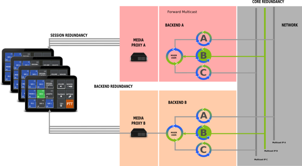
The first level of redundancy is session redundancy. Sessions span over different clients, based on the user login and role selection. Within the session all state changes are synchronized based on user broadcast messages. A switch from one client to another will allows seamless operation of VoCS services.
Second level of redundancy is backend redundancy. A client may connect to more than one backend at a time and synchronizes the states within different backends. This way a switch from one backend to the other will allow seamless operation of the VoCS services.
Third level of redundancy is inner core redundancy based on the Voiceloops, which are transmitted over multicast messaging. Once the audio path leaves the media proxy a multicast IP is used for media transmission and multiple mixer services from different backends may listen to the same multicast IP to generate the mixed stream.
Session Redundancy
Session redundancy is a special redundancy concept for openvocs. A session originates with user login. Once the user is authenticated and authorized the client of the user becomes part of a session. Each client is identified over a unique id. Within a session each action e.g. state changes will be synchronized. Each client will also have a dedicated state machine for Voiceloop states as each client login will be connected with a dedicated mixing service. Each client need to interact with it’s own mixing service to set the states the user has selected. Therefore each client to switches states independently.
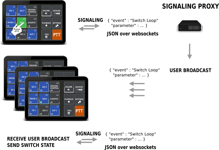
For synchronization a user broadcast is used. This broadcast will forward any state change information to any client connected. Each client will check if it is the originator of the broadcast based on the client id. If it is the originator no additional action needs to be performed. If the client is not the originator of the broadcast it will check its own state in correlation to the state of the broadcast message. If the state is different it will send a corresponding switch command to the backend. This way state switches are distributed to all clients within a session.
Each client switches the states independently from each other soley based on the user broadcast send.
Example of session redundancy:
Client A,B and C are in a session based on the same login information (same user, same role). The user switches on Voiceloop 1 at client A. Once the switch command arrives a the frontends signaling server a broadcast message is generated and distributed to all clients within the session.
Client B and C will recognize they are not the originator of the broadcast based on the client ID included within the broadcast message. They check the state of the Voiceloop 1 and will identify the Voiceloop is not switched on. As the broadcast contains a switch on command both clients will generate a Switch on message and send the message to the signaling server. The signaling server forwards the request to the clients mixing service and generate a new broadcast with the state Voiceloop 1 on. This broadcast is again distributed to all clients A,B,C, which will check if it’s own state for Voiceloop 1 is set to on. Once all clients have switched the Voiceloop 1 to on, no more messages are generated and all will have the same state.
Session redundancy is persisted within the backend. After logging out of all clients the session is still present within the frontends database. Once the user logs in again the states of the session will be distributed to the client, this time without any client id, so the client checks if it has the same states and if not send the switch commands for all Voiceloops.
This type of session redundancy is a new concept for Voice Communication Systems. States are syncronized between all clients based on the broadcasts messages. Switching from one client to another will allow seemless operations, as the participation states for Voiceloops are always the same within the session.
Backend Redundancy
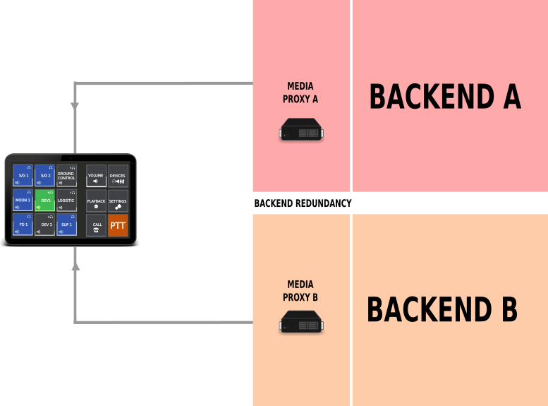
Backend redundancy is quite simple. A client connects to more than one backend at a time and will send all switch commands to all connected backends. This way the mixing services are synchronized within different backends.
The client simply syncronizes it’s own states within the different backends. Currently two backends are supportet in parallel. This forms a full backend recovery system.
To prevent echos and feedbacks the client has only one backend active at a time. Active means the audio path of the microphone is connected to one and only one backend at any time.
A user may switch the audio path to a different backend within the control menu of the client. Due to inner core redundancy the output of all Voiceloops is synchronized within different backend connections. So there is no difference in the audio received, but a difference in the path the audio is transmitted to the system and a difference in of the whole backend used.
This way backend errors or issues may be recovered by a backend switch on user command.
Inner Core Redundancy
To introduce inner core redundancy we start with the audio path of a connection. Each audio connection from a client is terminated at the media proxy. From client to proxy the audio path is a secured singlecast connection. The proxy forwards the audio to the Multicast IP of the Voiceloop.
Voiceloop selection is done by signaling over the signaling proxy. Whenever a Voiceloop is selected for talk, the signaling proxy communicates with the media proxy to switch the Multicast IP on for transmission. Once the transmission is switched on, the proxy will forward any audio received to the respective Multicast IP.
The mixing services of any users will receive the audio via Multicast transmission and mix the stream for reception of clients. Reception is done with forwarding a stream from the mixer service back to the media proxy on a dedicated pre coordinated port. Every audio received at that port is forwarded by be media proxy to the client.
Due to the use of Multicast between the media proxy and the mixer services different backends with different mixer services will receive the same stream as long as they are listening on the same Multicast IPs.
This is inner core redundancy. Different backends receive the same audio at the same time based on usage of multicast network connections for Voiceloop distribution.
This redundancy concept allows multiple backends to be in operations in parallel.
Network Redundancy
Network redundancy is implemented, according to the GSOC network management rules, with dual link networks. Each component must be connected over two network interfaces with interface bounding activated. This way maintenance of the network will have no impact to operations of the service running on top of the links. In our case the VoCS services.
Having a redundant network link makes network path failures highly unlikely.
Network connections of a console should be cabled with different switches for each link of the client hardware. This way a switch error will have no impact to operations. Within the backend each connection is done with dual link dual switch connections too.
The whole network layer is duplicated at layer 2.
openvocs systems architecture
The Openvocs core architecture is composed of a frontend facing core and a backend core. The frontend facing core includes 3 components.
- a webserver
- a signaling server
- a media proxy
A client connects via HTTP to the webserver and downloads a HTML5 based software client. This software client connects to the core systems signaling server via websockets and to the media proxy via a WebRTC connections. Websockets are used for signaling information like state changes within a Voiceloop (e.g. Switch on or off a Voiceloop or change the volume of some Voiceloop). WebRTC connections are used for media distribution between the client and the backend.
The components Webserver, signaling server and media proxy build the frontend connector of the core system and are primarily used for Media Setup and Media Channel (Voiceloop) selection.
The inner core system of openvocs is pretty simple too. We use Media Mixing Microservices, which are controlled by the frontend via signaling messages. Media distribution within the backend is done by Multicast. Each Voiceloop has a dedicated Multicast IP. A Mixing Service will collect all Voiceloops a user has selected and mix a stream of all of the Voiceloops. The stream is forwarded to the media Proxy, which forwards the mixed stream via WebRTC back to the client. The incoming client voice stream at the media proxy will be forwarded to the Multicast Groups of the Voiceloops selected for Talk. Each client connection uses a dedicated media proxy session and mixing service.
Each openvocs system is composed of a 3 LAN infrastructure. The outer LAN or WAN is where clients are located. This LAN segment is seen as unfriendly and all messages are encrypted by default. The inner LAN of openvocs is used for command and control actions and must be seperated by the client LAN. Within the command and control LAN services will be connected and assigned within specific client sessions. The 3rd LAN infrastructure is the multicast audio LAN for transmission of audio channels.
At the border between WAN and LAN are the ov_mc_vocs instance, as well as the ov_mv_ice_proxy instances. ov_mv_ice_proxy services are Session Borders for WebRTC connections. They control the media flow within the system. Each ov_client instance will be connected to one ov_mc_ice_proxy service and form a dedicated endpoint within the instance. These endpoint is the transmission node of media streams.
Next to multiple ov_mc_ice_proxy services the system used a ov_mc_mixer microservice architecture for media mixing. These mixers are idle by default, but may be assigend within a user session to serve a dedicated client endpoint mit media mixes.
The last service within the core system is the ov_mc_vad service, a service responsible for voice activity detection and information.